What were they thinking?
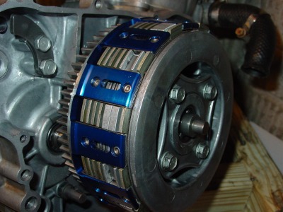
Both Unitized Kawasaki rear ends I bought had bad input shaft bearings. One rear end still rotated smoothly by hand, but the other was just shy of being locked up.
Guess which oil guide belonged to each rear end:

Not sure how the designers/engineers thought any oil would get to this bearing!? Oil guide blocking the bearing on one side:

Governor sprocket on the other side:

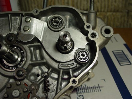
At least the other side has a little room for oil to get to the bearing. The clutch side bearing of both rear ends was in much better shape. I’m sure it was still out of spec, but it wasn’t obvious to the naked eye.

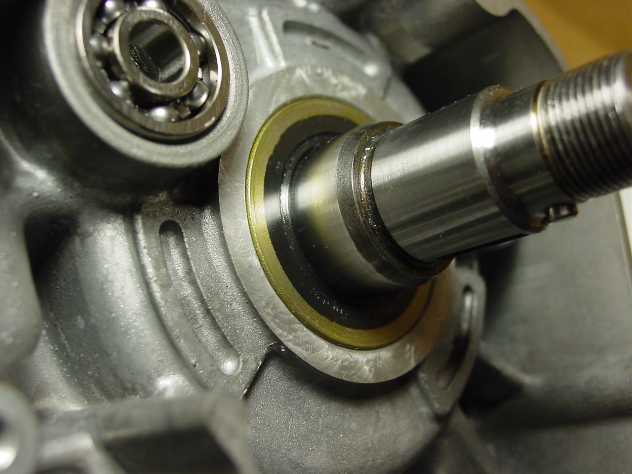
This is the governor side bearing from the rear end that was toast. The inner race shouldn’t be able to do that.

When that happens, things start rubbing that shouldn’t:

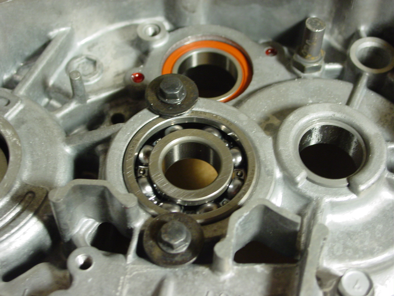
So Club Car’s solution to this bad design are sealed bearings:

I’m going trust this over what was used from the factory:

Being very careful, got the seals removed:

Grease in the other bearing:

Got all the grease out and ready for the red stuff:

I know you can over-pack a bearing with grease, but I figured that they used the bare minimum at the factory. With the factory grease being dark in color, it was a little tough to gauge just how much was in there. So I tried to add as much as I could while still allowing some room for extra grease to move into as the bearing got some use.

Time will tell how well this holds up.
One EXP conversion done, working on two more
The parts needed to make a few Rekluse conversions:

One is done and out the door today. Just waiting on a few parts to finish the others.

2016 Summer Project – 1992 Gas Club Car build
Bought this in June 2016. This is part of the reason I didn’t do any riding over the summer. That and it was really stinkin’ hot. Most of my time and all free money went towards this project.

Tear down:


24 years of oil, dirt, grass and twigs:


New engine:

Machined driven clutch and 8:1 gears:


The kids have been driving this to school for a couple of months now. With the 8:1 gears, it will do about 22-23 MPH at around 3,000 RPM. The engine could run safely at 4,000 RPM, but teenagers don’t need to be going that fast on most of the paths.


NoToil comparison
After using the FilGuard filter I bought a while ago, I wasn’t that impressed. But to be fair it was exceptionally dusty and the dust was so fine that it lingered in the air a long time.
Back when I did my air filter test, the NoToil filter performed very well. Thinking that all NoToil filters where the same, I ordered one of the pre-oiled ones:

Right out of the bag I was surprised:

Years ago I used NoToil oil but had oil settle to the bottom of the filter and drip in the airbox. I thought it was just be over-oiling, but I read complaints from others as well. I stopped using it. I am certain the machine that applies the oil in the factory is putting on the bare minimum, so I wasn’t expecting to see it settle out in the bag.

Without opening the inner bag, the filter material itself looked different than the one I tested years ago:

I went into the other room and turned the desklamp over:

I wasn’t liking what I was seeing:

I called RockyMountain up and got my return authorization for the pre-oiled filters I bought. A quick check on eBay and I found a non-oiled NoToil filter. A few days later this is what I received:


A quick side-by-side and you can easily tell that the foam isn’t the same between the two:

Nothing special about the sealing surface like on the Moose filters:

Now this is what I was looking for:

Seems like you give up quite a bit for the convenience of not having to oil the filter.

Letting the oil flow
As I’m putting the 220 together, this was a good time to modify the clutch hub I have been using. One of the used YZ clutches I bought a while ago came with a Hinson hub. That hub had a lot of big oil holes in it:

(click picture to enlarge)
The stock hub has 4 small holes:

(click picture to enlarge)
So without going too crazy, I went from 4 small holes to 16 larger ones:

(click picture to enlarge)
That is more like it

(click picture to enlarge)
Looks like I won’t be needing to hand-cut any gaskets for a little while now:

(click picture to enlarge)
HBR-CSRS #392 installed
More pictures HERE:

(click picture to enlarge)

(click picture to enlarge)

(click picture to enlarge)

(click picture to enlarge)
(click picture to enlarge)

(click picture to enlarge)

(click picture to enlarge)
Cleaning the KIPS
I had some of this cleaner that I was looking to get rid of so I thought I would try it on the KIPS parts. Started soaking just this part:

(Click picture to enlarge)
Then added some more and let them sit overnight. It got off a lot of the gunk,

(Click picture to enlarge)
but it didn’t get all of the heavy carbon build-up:

(Click picture to enlarge)

(Click picture to enlarge)

(Click picture to enlarge)

(Click picture to enlarge)
I went to a fine wire wheel and had to work to get this stuff off:

(Click picture to enlarge)
Soaked the rest of the KIPS in more of the combustion cleaner and they came out pretty clean:

(Click picture to enlarge)

(Click picture to enlarge)
In time we’ll see how well the carbon does/doesn’t stick to the more polished surfaces. If I was going to polish this correctly, I would have had to have sanded out more of the metal to get rid of the imperfections for a nice surface. But I didn’t want to remove metal and screw with the tolerances of the parts. So all of the polishing was done with a buffing wheel. Not a mirror finish, but it should be a bit “slipperier” than it was before:

(Click picture to enlarge)

(Click picture to enlarge)
A final clean-up in acetone and all ready to install:

(Click picture to enlarge)
220 KIPS bore clean-up
It is not uncommon for some excess plating to buildup inside the bore of the KIPS system when the cylinder gets replated. The left side isn’t a problem, but the right side that uses the o-ring on the exhaust rod can cause binding. Removing the o-ring is not the proper fix.
I kept the old o-ring on and tested the cylinder to see how much resistance was on the rod. I didn’t want to tear up the new o-ring.

(Click picture to enlarge)
Not too bad, but it could be better. Featuring the HBR Power Valve Bore Resurfacer, or HBR-PVBR for short. Made from the highest quality materials, machined to the tightest of tolerances:

(Click picture to enlarge)
I started with some 320 grit wet/dry sandpaper:

(Click picture to enlarge)

(Click picture to enlarge)

(Click picture to enlarge)

(Click picture to enlarge)
I moved the HBR-PVBR in and out of the bore several times while running the drill. I checked the exhaust rod for proper operation. I finished the process with 400 grit wet/dry sandpaper. The rod moves smoothly with no hang-ups or unnecessary resistance.
Got the bottom end of the 220 put together
More pictures and details HERE.

(click picture to enlarge)

(click picture to enlarge)

(click picture to enlarge)

(click picture to enlarge)

(click picture to enlarge)

(click picture to enlarge)

(click picture to enlarge)
(click picture to enlarge)

(click picture to enlarge)

(click picture to enlarge)

(click picture to enlarge)

(click picture to enlarge)

(click picture to enlarge)

(click picture to enlarge)

(click picture to enlarge)

(click picture to enlarge)

(click picture to enlarge)

(click picture to enlarge)

(click picture to enlarge)
Soda blasting cases
With all the modifications done to the cases, it is time to clean them up. The Harbor Freight soda blaster works surprising well.

(click picture to enlarge)

(click picture to enlarge)

(click picture to enlarge)

(click picture to enlarge)

(click picture to enlarge)
Done with the soda,

(click picture to enlarge)
Soaking in hot, Dawn filled water to get rid of all the baking soda:

(click picture to enlarge)
Well I thought soaking them for a while and then using the handheld sink sprayer would have dissolved/removed all the baking soda. But after speed drying the cases in the oven, I was wrong. There was still baking soda in some of the blind bolt holes.

(click picture to enlarge)

(click picture to enlarge)
So back to the utility sink. This time I bought a tooth pick and poked it around in all the bolt holes while spraying it with the handheld sprayer. Speed drying in the oven again and finally the cases are clean.
(click picture to enlarge)
Final truing of the HBR crank
I’ve had this crank I rebuilt a while ago stored away waiting for a bottom end to put in. I thought I’d check the run-out one last time before I installed it. It was well under specs, but I thought I’d push my luck and see if I could get it better.
I put the indicators as far out as possible to get the best reading.

(click picture to enlarge)
Kawasaki didn’t make it very easy on the clutch side. Between the keyway slot and the locator pin hole for the water pump gear, there isn’t much real estate to work with:

(click picture to enlarge)
The flywheel side didn’t have as many obstacles, but with the taper, any later movement would throw the reading off:

(click picture to enlarge)
After just a handful of calculated whacks, I had the indicator on the flywheel side just barely moving and the clutch side was just under .001″ out.
I didn’t set-up the indicators exactly like outlined in the manual, but this orientation should highlight the run-out a little better than what is shown in the manual.

(click picture to enlarge)
Both indicators barely moved. Even with the limitations of my set-up and indicators, this should be a long lasting and smooth running crank.

HBR – Crank Seal Retainer System (patent pending) Model 392
Logic told me that the crank seals weren’t going to blow out of the cases with the retaining lip removed. But I had the time, material and paranoia to try to add some peace of mind to this modification. Born is the HBR-CSRS model 392.
For the clutch side, I used some acrylic to mock-up what the retainer would look like:

(click picture to enlarge)
Originally I was going to use 1/2″ aluminum and machine away most of it for the necessary clearances. I wouldn’t have to bend anything and the differences between where the retainer bolted to the cases and where it rested against the seal would be easy enough to work out.

(click picture to enlarge)
But I took a quick stab at making one out of thinner aluminum and seeing if I could get the bends correct. I think it was more luck than anything but I got this worked out:

(click picture to enlarge)
I added this drain channel to the backside. This isn’t so much for oil to drain out but rather to give the sediment from the worn clutch friction material a place to drain away. It just seems like a bad idea to have that abrasive material collecting near the crank seal.

(click picture to enlarge)
Other than removing the factory cast retaining lips,

(click picture to enlarge)
I put this notch in the alignment dowel part of the case:

(click picture to enlarge)
The retainer fits into this notch,

(click picture to enlarge)
And then bolts into place on top of the existing oil receiver:

(click picture to enlarge)
Inside view:

(click picture to enlarge)
Flywheel side was a little easier. Using a spare, I removed the electronics and started with this:

(click picture to enlarge)
Put it on the scanner and cut out a template:

(click picture to enlarge)

(click picture to enlarge)

(click picture to enlarge)
After some work I had this:

(click picture to enlarge)

(click picture to enlarge)
Ready to bolt on:

(click picture to enlarge)

(click picture to enlarge)
With the retaining lip removed:

(click picture to enlarge)
Installed:

(click picture to enlarge)

(click picture to enlarge)
Now I’ve got the peace of mind that the seals won’t push out, yet with the removal of a few bolts I can still service them.
Splitting the Rekluse EXP test engine
With the last EXP conversion shipped out, I thought I’d take a few minutes and split the engine I used to test fit the conversions on. I think I used this on 15 conversions:

(click picture to enlarge)
So here we go, getting the flywheel off:

(click picture to enlarge)

(click picture to enlarge)

(click picture to enlarge)
Before you start trying to split the cases, double-check that you have removed 11 case bolts:

(click picture to enlarge)
As usual, a nice “pop” that makes you think you just broke something:

(click picture to enlarge)
One I get the “pop” and initial separation at the crank side of the cases, I start tapping the rear of the cases with a rubber mallet to get them separated.

(click picture to enlarge)
Separating and tapping a little at a time making sure gap stays consistent between the front and rear of the cases:

(click picture to enlarge)
Just about there:

(click picture to enlarge)

(click picture to enlarge)
Got lucky on this one that both crank bearings stayed in the cases. Usually one stays on the crank.

(click picture to enlarge)
Cylinder arrived today
My 220 cylinder came back from PowerSeal today.
I shipped it off on December 30th (Wednesday).
It was delivered on January 2nd (Saturday).
Received an email from them on January 4th (Monday) letting me know they received the cylinder – nice touch. Emailed stated that turnaround time was currently 9 days.
Received a call on January 11th (Monday) that the cylinder was done. $207 shipped back to me.
Cylinder was delivered on January 13th (Wednesday).
They send it back in the same box with the same packing you shipped it in.

(click picture to enlarge)

(click picture to enlarge)

(click picture to enlarge)

(click picture to enlarge)

(click picture to enlarge)

(click picture to enlarge)

(click picture to enlarge)

(click picture to enlarge)
Case modification – replace crank seals without splitting the cases
Better way HERE.
I’ve been researching this for a while and finally took the plunge. Yamaha and Honda allow you to replace the crank seals without splitting the cases. But these lips that Kawasaki manufactured into the cases prevents that.
Partial lip on flywheel side:

(click picture to enlarge)

(click picture to enlarge)
Full lip on clutch side:

(click picture to enlarge)

(click picture to enlarge)
Honda doesn’t use a retainer on either crank seal:
http://www.allthingsmoto.com/forums/f-235/round-three-92-01-cr250-engine-build-46010/
And Yamaha only uses a retainer on the clutch side (~5:20). At about 5:46 of this video, he just pushes the crank seal in with his fingers. I can’t tell from any of the 3 RMATV videos, but the stator could serve as a seal retainer. But I did notice that the seals Yamaha uses are different than what the KDX uses. No way are you installing the KDX seals with just your fingers.
The more I’ve thought about it, I’m thinking those “lips” are more of stops that put the crank seal in the correct location. If there was concern about the seals moving and popping out, I would think there would be an equal concern with the seals moving inwards and blocking off the oil passage. I’ve yet to see a seal that wasn’t seated against the lip, so I highly doubt that they move.
So here we go . . .
Flywheel side removed:

(click picture to enlarge)
Clutch side removed:

(click picture to enlarge)
Neat little drill bit
I bought this drill bit a while ago from eBay. It was made in Poland and didn’t cost that much. I wasn’t sure how it would work out and I finally have a chance to try it out on my 220 build.
The first part is a 15mm guide and the cutting part of the bit is 17mm.

(click picture to enlarge)

(click picture to enlarge)

(click picture to enlarge)
Worked very well:

(click picture to enlarge)

(click picture to enlarge)
Blind bearing removal – no puller required
You don’t need too much to get the blind bearings out of the cases. What you are trying to do is to force a material back behind the bearing so it applies pressure to the bearing to push it out.
I was fortunate enough to have some leftover parts that I could use to get the bearings out. You could use anything as long as it fits tightly within the inner race of the bearing. You don’t want the material you are using to escape between the inner race and whatever you are using to force the material back behind the bearing.

(click picture to enlarge)
I use plumbers putty:

(click picture to enlarge)
And some heavy duty packing paper. Newspaper can work OK, but when you wet it down, it tends to disintegrate much easier than this brown packing paper.

(click picture to enlarge)
The transmission bearing: For this one I use plumbers putty, it makes quick work of removing the bearing. Fill the bearing up:

(click picture to enlarge)
Then hammer it in:

(click picture to enlarge)
Keep repeating that process of adding more putty and hammering it in until the bearing starts to lift out:

(click picture to enlarge)

(click picture to enlarge)

(click picture to enlarge)

(click picture to enlarge)

(click picture to enlarge)

(click picture to enlarge)

(click picture to enlarge)

(click picture to enlarge)
Water pump bearing: I did a little experiment here, I used a combination of the brown paper(dry) and plumbers putty. It is a little difficult to see, but I’ve packed some of the dry brown paper down into the bearing. This is to try to keep the plumbers putty from getting forced up through the openings in the bearings.

(click picture to enlarge)
Add some putty:

(click picture to enlarge)
Hammer it in and keep repeating:

(click picture to enlarge)

(click picture to enlarge)

(click picture to enlarge)
The leftover mess:

(click picture to enlarge)

(click picture to enlarge)
The KIPS governor bearing: I’m using just the wet brown packing paper on this. Same approach as the other bearings.

(click picture to enlarge)

(click picture to enlarge)

(click picture to enlarge)

(click picture to enlarge)

(click picture to enlarge)
Got a little carried away with the case sealant
How it came from the factory:

(click picture to enlarge)

(click picture to enlarge)
Crank Rebuild
My first attempt at rebuilding a two stroke crank. I’m starting with this H-series KDX crank:

(click picture to enlarge)
A few minutes with a fresh cut-off wheel on the angle grinder:

(click picture to enlarge)
Remember to press the crank pin from the outside-to-inside. You don’t want to press the crank pin out so the cut portion has to pass through the crank web:

(click picture to enlarge)
Using a Pro-X (OEM) crank rebuild kit. $58 on Amazon:

(click picture to enlarge)
First step installing the crank pin:

(click picture to enlarge)

(click picture to enlarge)
Bearing and washers on:

(click picture to enlarge)
Because I don’t have a nice jig that ensures nearly perfect alignment like the crank builders do, I pressed the other crank web on in steps. Once I got it started, I put in on the v-blocks and made adjustments to get the run-out below .001″. Because the crank pin wasn’t fully seated, these adjustments took very little force. I repeated this partial press/adjustment process a total of three times. This is what the crank looked like after the 3rd press:

(click picture to enlarge)
Final press:

(click picture to enlarge)
Specs on side clearance:

(click picture to enlarge)

(click picture to enlarge)

(click picture to enlarge)
A quick video showing my run-out during part of the process:
Back to the KX250 silencer
I am going to go back to the KX250 silencer, for a while at least.
First step is adding the spacer, like I did HERE. This time I am going to go with aluminum.
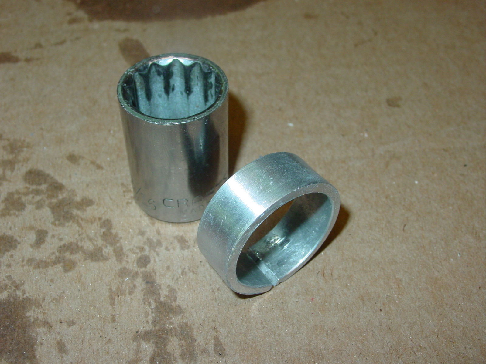
(click picture to enlarge)
I had to pry it apart just to get it started:

(click picture to enlarge)
Then tapped it on the rest of the way:

(click picture to enlarge)

(click picture to enlarge)

(click picture to enlarge)
Ready to go:

(click picture to enlarge)